Configuring VOLO Controllers
This article describes how to configure a VOLO Controller.
Coming Soon!
Connecting the Master Controller
Wire the components to the VOLO Master Controller as shown in the Wiring Diagram.
Power up the unit and wait for the OK LED heartbeat. If there is a fault with the installation or the unit then the diagnostic LEDs may well show the fault type, enabling you to report or rectify the problem before proceeding.
To confirm relay activation for the locking hardware, press the exit button or in the absence of an exit button, place a test jumper between the 0v and exit terminals. Once the exit button is pressed or the jumper temporarily placed, the lock should release.
When using Paxton readers, the reader's default indication has all the LEDs on. Access granted is denoted with a single flashing Green LED. Access Denied is a single flashing Red LED. The green reader LED should flash when the exit button is pressed.
Configuring the Master Controller
The VOLO Master unit may require configuration and initialisation before use. To do this will require a Windows PC or laptop with USB ports and internet access, or having the proper installer tool previously installed.
Install the Installer Tool software. This is available to download from the Help page of your installer login to the VOLO cloud. You may wish to create a desktop shortcut for this application.
tip
Always ensure you have downloaded the latest version of the Installer tool to ensure you have the most recent version of firmware. The latest version is bundled with the Installer Tool application.
Remove the power from the unit.
caution
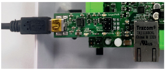
Make sure the adapter is plugged into both rows of the header on the PCB before you proceed (see image below for proper placement and connection).
Power up the controller with the installer tool adapter connected. Note your PC or laptop may need to download a device driver so allow this to complete first. Now run the Installer Tool by double-clicking the Installer Tool application.
Click on settings and select the COM port that your PC or laptop has assigned to this device. The drop-down box lists all available COM ports.
tip
You can confirm the COM port assigned by your computer by navigating to the Windows 'Device Manager' and then se lecting 'Ports (COM & LPT)'
Now click on 'View Device Details' and then on the 'Get Details' button. Follow the instruction by power cycling the Master unit so that it goes into its bootloader and provides the required details.
tip
You can power cycle the Master unit by removing and replacing the two pin power plug at the top right of the controller (a two pin plug) marked l 2V-24V and OV.
You will not need to do anything with this information at this point. Make a note of how this information is obtained as it will be needed should the wiring label be lost or misplaced. This information may be required by KMC technical support for diagnostics and troubleshooting.
Firmware Update
It is important to update the firmware to the latest available version before proceeding further.
Select the 'Update Firmware' button.
Power cycle the Master unit as described above to start the firmware update.
If you receive an 'access to the port XX is denied' error message from Windows, click the OK button and power cycle the unit again to attempt to re-start the firmware update. The firmware update will take a minute, once the green bar has progressed to fill the space, the update is complete.
You can check the version of firmware installed using the 'View Device Detail' option described in the previous section.
tip
It is useful to know which version of firmware is installed whenever you contact Technical Support.
Please store the adapter in a safe place. You will need this for your expansion controllers along with any future upgrades to this Master Controller.
If you are updating firmware on a unit already in use you will need to re-instate this controller in the software following the firmware update.
Communication Settings
The 'Communication Settings' button displays a number of settings with default values (see below). You can query the exisiting settings and edit those if you wish.
You may select the Default Communication Method from the drop-down list.
The default setting is 'Auto' meaning that the controller will attempt to use the TCP/IP Ethernet connection as long as one is available. If the Ethernet connection is not present, or fails configuration, the controller will automatically use the modem.
Note that mobile charges may apply and use of this will require the purchase of the Volo SIM licence. You may also choose to set the communication method to modem or Ethernet only, depending on the customer and site requirements.
You may manually configure your Ethernet connection on a static IP address should you not have a DHCP server available.
Please note that the Master Controller does not require a fixed or static IP address to communicate and can utilize DHCP addressing. If you have DHCP you do not need to set any of the Ethernet settings. Should you not have a DHCP server you will need to contact the site IT Manager to obtain an IP address and other connection information.
Once you have completed the setup then press 'Send to Device' and follow the power cycle instruction. You should now close this application, turn off the power to the Master unit and remove the adapter and USB cable.
::tip Remember to always download the latest version of the installer tool to ensure you have the most recent version of firmware to in stall. :::
You have now completed the initial configuration of the Master Controller, power cycle the unit and log into your VOLO account and follow the instructions from the Quick Start Guide for assistance with setting up the controller in your customer and site.